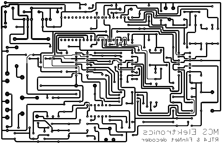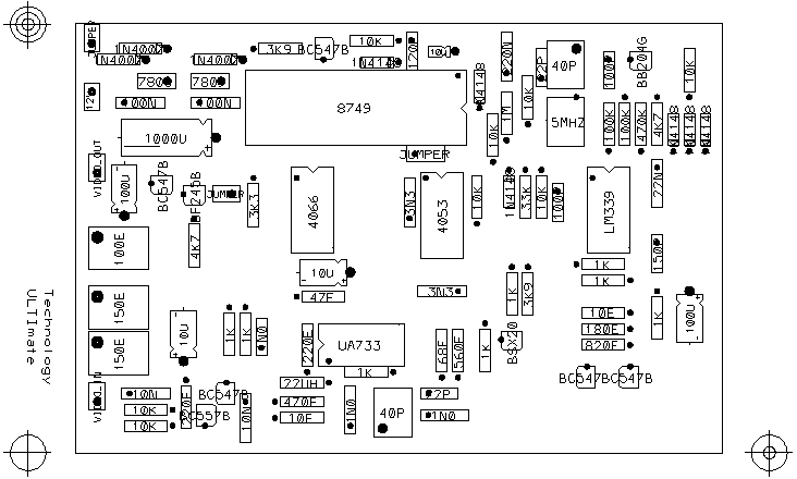

Originally it was developed for connecting to a satellite receiver, but it
works well on a cable receiver! but here in holland RTL4 is unscrambled on
the cable.

The adjustment.

This is very simple. Start with connecting pin 35 of U7 (8749) to ground.
turn R39 and R26 halfway, and R38 to gnd, and C9 and C6 to half.
apply a normal videosignal to the input (ie unscrambled) and connect the
output to a monitor/modulator or TV/receiver input or a ossiloscope.
apply 12V to the supply input (J1). Now a picture will appear, rolling over
the screen. turn C9 till the picture slowly scrols to the left, about 1 roll
per 2 seconds. now turn R38 till the picture stops, and turn C6 to the middle
of the 2 ends where the picture begins to scroll. try to turn R38 a bit back
to ground if the hold-region is to big.
Now apply a encoded signal, ie FilmNet or RTL4, and turn R39 till the
blacklevel is equal to the blanking-level, or black appears to be normal on
the screen, not to black, and not to grey.
finaly adjust R26 so that the contrast of the picture appears to be normal.
now remove the power and the connection between pin 35 of U7 and ground.
Turn R38 to ground. Turn on the power, and turn R38 slowly untill the picture
appears, turn R38 a little bit further.
ok, now connect a voltmeter to the junction between R12 and R13 and turn C9
till the voltage is about 3,80 Volts. Remove the voltmeter. (Note that I use
a voltmeter with a Ri of 10Mohm.)
Now switch to RTL4, and turn R38 so that the picture stays positive.
This does NOT apply to cable or FilmNet only use.

Well, for the electronics here a explanation of the adjustment points.
R38  Input level to chroma detector.
R39  Input level of the CVBS signal, adjust so that the blacklevel is equal
     to the blanking level. (scope on rastersync.
R26  Output level of the decoded CVBS signal. maximum is about 2.6Vtt
C6   Chroma filter resonance. adjust to 4.43 MHz.
C9   VCO free-running frequency. see TP.

well, success with the building of this decoder! and watch for the ATNDOC's!


----  List of Components  ----
      *** Capacitors ***

          C11,C25 = 22P         CRM
          C6,C9 = 4-40P         TRIMMER
          C8,C16 = 100P         CRM
          C24 = 120P            CRM
          C17 = 150P            CRM
          C2,C5,C12 = 1N0       MKM
          C14,C15 = 3N3         MKM
          C1,C3 = 10N           MKM
          C7 = 22N              MKM
          C22,C23 = 100N        MKM
          C18 = 220N            MKM
          C10,C13,C20 = 10U     ELKO
          C4,C19 = 100U         ELKO
          C21 = 1000U           ELKO

      *** Diodes ***
          D1,D2,D4,D8,D9,D10 = 1N4148
          D3 = BB204G
          D5,D6,D7 = 1N4007

      *** Diversen ***
          J1 = 12V
         JP1 = VIDEO_IN
         JP2 = JUMPER
         JP3 = VIDEO_OUT
         JP4 = JUMPER
         JP5 = JUMPER
          L1 = 22UH
          X1 = 15MHZ

      *** Halfgeleiders ***
          Q1 = BC557B
          Q2,Q3,Q4,Q6,Q7 = BC547B
          Q5 = BF245B
          Q8 = BSX20
          U1 = LM339
          U2 = UA733
          U3 = 4066
          U4 = 4053
          U5 = 8749HC


After you print yourself the circuit boards you're almost done.
Now just program the 8749(8749HC)