CABLE DESCRAMBLER
FOR THE GATED SYNC SUPPRESSED SYSTEM
THE CONTENTS OF THIS REPORT ARE FOR INFORMATIONAL AND EDUCATIONAL PURPOSES
ONLY.
THE ILLEGAL USE OF THE INFORMATION CONTAINED IS STRICTLY FORBIDDEN BY LAW.
WE ASSUMES NO RESPONSIBILITY FOR THE ILLEGAL USE OF THIS INFORMATION.
THEORY
Before we get into the actual assembly steps, we should review the theory
of gated sync suppression so that you may understand descrambling it better.
Any TV signal is a complex combination of video as well as timing information.
Your TV receiver sorts out this information by sampling the level (in %
of modulation) of the complex signal and displaying a picture on the screen
in relation to this signal. Figure 1 shows the scope pattern for
a normal TV signal. The high points of the signal are called sync pulses
and represent 100% modulation, the next highest points are blanking pulses
(about 75% modulation); the lowest points represent the video portion of
the signal and range from 12.5% to 70% modulation. The center pattern in
Figure 1 illustrates the scrambling wave which gates a variable
gain amplifier or attenuator network to reduce the sync and blanking pulses.
This reduction causes your scrambled signal because your TV setís timing
circuits have no regular pulses to lock onto. Instead it now locks onto
random video spikes because these spikes are the highest modulation peaks
your set receives. This is illustrated in the bottom pattern of fig. 1.
Some scramblers suppress both the horizontal and vertical pulses;
others suppress only the horizontal. This descrambler will work on either
system.

In order for a descrambler to work, it must receive decoding information.
This information is sent on a scrambling signal which is inverted and amplitude
modulated (AM) on a carrier of a particular frequency. This frequency is
generally outside the frequency band allocated to the cable companies.
This scrambling signal is often referred to as the pilot signal
and the frequency it is on is referred to as the pilot frequency.
The standard pilot frequencies are listed in Chart A and are in order of
most common at the top to least common at the bottom. Your descrambler
will work on any of these frequencies but some capacitor values and the
number of turns in the coils will vary depending on the frequency you wish
to descramble.
DETERMINING YOUR PILOT FREQUENCY
The easiest way to determine your pilot frequency is to ask your local
cable company. Unfortunately some cable companies consider this information
top secret. Fortunately it is not difficult to determine your pilot frequency
once you know what to look for and if you have some additional equipment.
Of course you could take a chance and build your descrambler for the most
common frequency (50.5 MHz) and hope that it is the one your cable company
is using, and it is easy to change from frequency to frequency by changing
coils and several capacitors.
UHF CHANNEL  PILOT FREQUENCY     RELATION TO CABLE CHANNELS       [:using block converter:]
42           50.5 MHz            This is 3.5 MHz below channel 2
53           114 MHz             This is 6 MHz below channel A
49           93 MHz              This is 27 MHz below channel A or 11 MHz above channel 6
50           99 MHz              This is 21 MHz below channel A or 17 MHz above channel 6
52           110.5 MHz           This is 10.5 MHz below channel A
52           108 MHz             This is 12 MHz below channel A
CHART A
A better way to determine your pilot frequency is with a piece of equipment
called a block converter. These block converters will take the cable TV
channels and convert them to the UHF band, They will also convert the pilot
frequency to a UHF channel, which makes it easy to determine exactly what
frequency it is. They are hard to find though. While watching the TV screen
and tuning through the channels in the UHF band (those listed in chart
A especially) you will find one which makes the screen go pure white. This
will be your pilot channel (or frequency). Lets take a look at this a little
closer. A pilot signal is a series of pulses not unlike a standard TV channel
pulse. The difference is that there is zero video level between the pulses.
Zero signal level on a TV signal corresponds to white on the TV screen.
So this is what you see when you tune to the pilot frequency, a pure white
screen. By noting what channel you have the TV set on when you get a pure
white screen and by comparing this channel to the ones in Chart A
you will know what the pilot frequency is. Once you know the pilot frequency,
building your descrambler is a simple job.
DESCRAMBLER THEORY
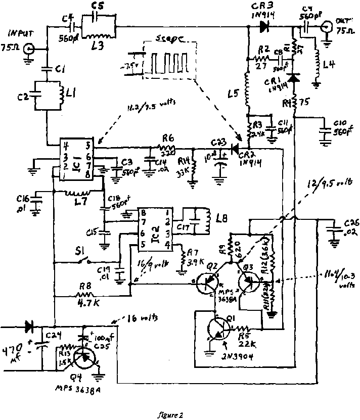
The operation of this descrambler is relatively simple. Refer to the schematic
diagram in figure 2. The input signal contains all the cable channels
plus the pilot signal and any other signals coming in on the cable. The
combination of C5 and L3 is a simple parallel tuned circuit tuned to the
pilot frequency. The combination of Cl, L1, and C2 is a notch filter tuned
as follows: The combination of L1 and C2 in parallel is tuned from 4 to
6 MHz above the pilot frequency. At the pilot frequency this combination
looks like an inductor and the value of C1 is chosen to resonate with this
equivalent inductor presenting a low impedance path to the pilot frequency
while presenting a high impedance to all other frequencies. As an example
Assume the pilot frequency is 114 MHz. At 120 MHz (the carrier of channel
A) a 12 pF capacitor has 111 ohms of reactance. We would choose this value
for C2. The value of L1 necessary to resonate with C2 at 120 MHz is .147
uH. At 114 MHz this parallel combination has an equivalent inductive reactance
of 1075 ohms. The value of C1 necessary to resonate with this inductor
at 114 MHz is 1.3 pF, so we would choose a 1.5 pF capacitor for our final
design. The pilot frequency then passes through the notch filter and into
the input of IC1 which is an RF amp chip with AGC control. The output from
IC1 then goes to the input of IC2 through a tuned circuit consisting of
L7 and C15. IC2 is a low level video detector chip. IC 2 has an RF stage
to which a filter consisting of L8 and C17 is added The resulting demodulated
pulse train comes off pin 5 of IC2 and is fed to a differential amp consisting
of Q2 and Q3. The output of the video detector is high enough to drive
the differential amp from cut off to saturation. The collector of Q2 drives
CR1 on and off and Q3 alternately drives CR3 on and off. Q1 prevents any
current from flowing through CR1 when Q2 is off (note the low resistance
load of Q2). When CR3 is on and CR1 is off, the RF signal passes from the
input to the output with very little attenuation. When CR1 is on and CR3
is off, the signal must pass through the "T' attenuator circuit consisting
of R1, R2 and R4. For the values of Rl, R2 and R4 used in the circuit,
the result is a 6db attenuation. This attenuation occurs during the video
interval between pulses and the output signal looks like a normal video
signal. Also taken off the collector of Q3 is the AGC voltage for IC1.
With the given values for R6, R14, and C23, the pulse level at the anode
of CR2 is held at about 7.5 volts.
The builder has two options for the power supply. You can either use
a 12 to 14 volt ac supply and diode D1, or you can use a 14 to 18 volt
dc power supply in which case D1 may be omitted. Only about 20 ma of current
is required by the circuit. Transistor Q4 along with R13 and C25 comprise
an active filter which reduces AC ripple to less than 20 uv. The on-off
switch S1 switches the B+ pin of IC2. When S1 is off, the output of IC2
(pin 5) is pulled high. Therefore, Q2 is off and CR3 is open and there
is only a small (less than 1 dB) insertion loss for the descrambler.
ASSEMBLY
Before purchasing any components we recommend reading the complete assembly
procedure and making a list of the components you will need for your pilot
frequency. All you will need to construct your descrambler will be standard
hand tools such as a drill, pliers, screwdrivers, wirecutters, etc. You
will also need some 60/40 rosin core solder and a 25 to 40 watt pencil
type soldering iron. Equipment wise, we recommend a high impedance multi-meter
(a VTVM or DMM) and an oscilloscope although the device can be constructed
and tuned without either piece of equipment. Before placing any parts on
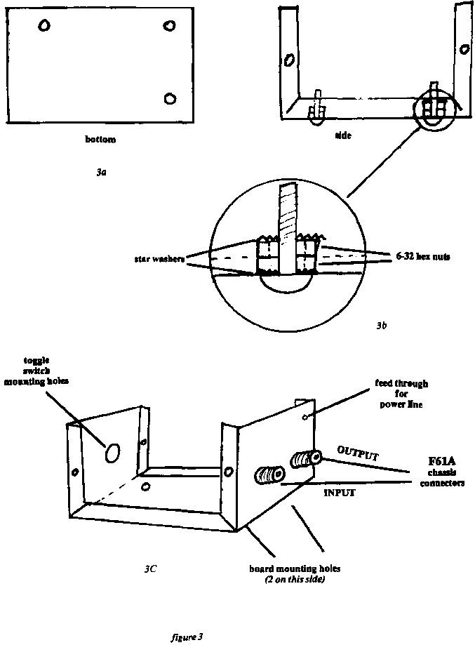
the board, prepare the chassis box to mount the circuit into. Figure
3 shows a cabinet made from either a Bud chassis box #CU2106B or an
LMB box #136. Figure 3a shows the three bottom mounting holes, the
position of these holes may be determined by placing the board on the bottom
of the chassis and marking the position of the 3 large mounting holes at
the corners of the board (be sure that the copper side of the board will
be down when it is mounted in the box). Figure 3b shows the three
mounting screws (3/4" x 6-32 round head machine screws). The two hex nuts
are used for spacers and the star washers provide a good ground. The board,
when finished, will be mounted copper side down on these screws and fastened
with hex nuts on each screw. Cautions if your star washers are too large
they may short one of the copper runners to ground.
Figure 3 shows the mounting position of the on-off switch S1,
and the two F61A coax connectors. Note: the F connectors are on the end
of the box with the two board mounting screws, and the switch is on the
end with one mounting screw.
ASSEMBLING THE BOARD
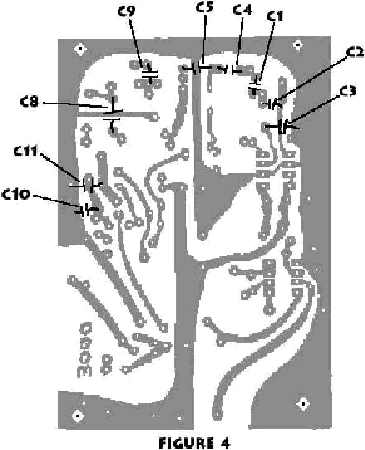
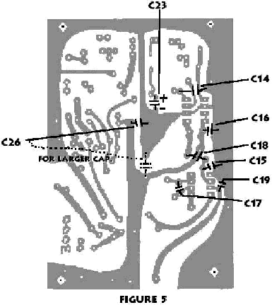
Drill all component lead holes with a #60 drill (.040). Figures 4 through
8 show all the component parts and the proper placement on the board.
In the figures you are looking at the top, or uncopper clad side. Be sure
to place the part leads in the proper holes. For each figure there is a
discussion and parts list describing the components for each pilot frequency
and alternate components. Read and understand the material before purchasing
any components. When inserting components be sure to keep the leads as
short as possible and the components as close to the board as possible.
Solder a 100 ohm 1/4W resistor in series with one lead. For the chart below
refer to figure 4.
 Component            Pilot                    Value         Notes
 C1                   50.5 MHz                 5pF           A 4.7 pF is acceptable
 C1                   90 to 114 MHzHH          1.5pF         A 1.8 pF is acceptable
 C2                   50.5 MHz                 24pF          +/- 10%
 C2                   90 to 114 MHz            12pF          +/- 10%
 C3, C4, C8           ALL                      560pF         100 volt disc
 C9, C10, C11         ALL                      560pF         100 volt disc
 C5                   50.5 MHz                 200pF         Ceramic or Dipped Mica
 C5                   90 to114 MHz             82pF          +/- 15%
NOTE: The operating voltage of these capacitors need be only 25 volts Capacitors
with higher operating voltages may be used but check the size and be sure
you can fit them an the board. Solder the above components to the board.
Be careful not to cover any unused holes. Clip off excess leads.
For the following chart refer to figure 5.
 Component        Pilot            Value       Notes
 C14, C26         ALL              .02uF       25 to 100 disc
 C16, C19         ALL              .01uF       25 to 100 disc
 C23              ALL              10uF        25 volt electrolytic, radial leads
 C18              ALL              560pF       100 volt disc
 C15              50.5 MHz         56pF        Ceramic or Mica
 C15              90 to 144 MHz    12pF        +/-10%
 C17              50.5 MHz         47pF        Ceramic of Mica
 C17              90 to 144 MHz    6pF         6.8 usable with tuning of L8
Electrolytic capacitors are polarized. The polarity is marked on the capacitor
with either a plus or minus sign or both. Be sure the polarity is correct
as shown in the diagram. Reversing the polarity will not only damage the
capacitor but could damage other components as well. Solder the above components
being careful not to cover unused holes. Clip off excess leads.
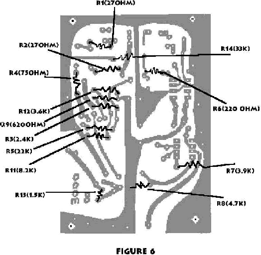
For the following refer to figure 6. In figure 6 the placement
of all the resistors is shown. All resistors are 1/4 watt 5% tolerance.
The values are shown on the figure next to the component number, most resisters
are color coded. If you are unfamiliar with the color code, we urge you
to refer to any basic electronics book. The resistor values are the same
for all pilot frequencies. Solder the resistors in place being careful
not to cover any unused holes. Clip excess leads.
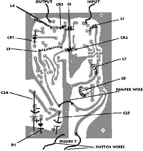
Refer to figure 7 for the following. Figure 7 shows the
placement of the coils and diodes. All the coils for this device are air
core and wound so that if you look down the axis of the coil and traverse
the turns clockwise, the pitch of the coil will be towards you. This is
shown in the diagram below. All coils are wound with copper enamel wire.
The enamel must be stripped off the leads of the coil in order to solder
the coil to the board.

Note also that the coil data states a number of turns plus 1/2. As shown
in the drawing, the turn count starts where the coil first bends. The 1/2
turn merely assures that both leads will face the same direction for easy
insertion. We recommend winding the coils on the butt end of a drill bit
of the proper diameter. All coils are wound close (no spacing between the
turns) although if they do expand it is not critical at this time. Also
in figure 7 the diodes (Dís or CRís) are shown. The drawing below
shows the symbol for a diode and a representation of what a real diode
looks like. The diode polarity is critical. The bar on the real diode corresponds
to the bar on the diode symbol as shown.

 Component       Pilot      Value               Characteristics     Notes
 C24             ALL             470 uF         25v electrolytic    Be sure polarity is correct
 C25             ALL             100 uF         25v electrolytic    Be sure polarity is correct
 D1              ALL             1N4001 or equivalent
 CRl, CR2, CR3   ALL             1N 914 or 1N4148
 L4, L5          ALL             32 1/2 turns #24 copper enamel wire 1/8 " inside diameter
 L3              50.5 MHz        3-1/2 turns
 L3              105 to 114 MHz  1-1/2 turns
 L3              90 to 105 MHz   1-1/2 turns, 7/32" inside diameter
 L1              50.5 MHz        13-1/2 turns
 L1              105 to 114 MHz  6-1/2 turns
 L1              90 to 105 MHz   7-1/2 turns
 L7              50.5 MHz        8-1/2 turns
 L7              105 to 114 MHz  5-1/2 turns
 L7              90 to 105 MHz   6-1/2 turns
 L8              50.5 MHz        8-1/2 turns
 L8              105 to 114 MHz  8-1/2 turns
 L8              90 to 105 MHz   9-1/2 turns

 [Remaining coils are wound with #22 copper enamel wire with a 3/16"diameter unless specified.]
Next insert the jumper wire shown in figure 7. This can be a clipped
off lead from a previously inserted component, Solder the above components
to the board at this time. Clip all excess leads. The input-output and
switch wires are now connected. These can also be clipped off leads from
other components. Just make sure they will be long enough to reach the
coax connectors and switch.
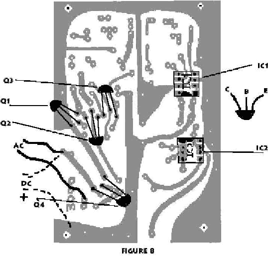
Refer to figure 8 for the following. The transistors and ICís
are inserted and soldered in this step. We sincerely recommend using transistor
and IC sockets for mounting these components to avoid heat damage from
soldering but they may be soldered in place if a heat sink and care in
taken. In either case be sure to place the correct leads in the holes to
be soldered or in the transistor socket holes. Transistors have three leads
labeled E, B and C. These may be written on the transistor itself or on
the package the transistor comes in. ICís generally have a circle or notch
on one side indicating pin # 1. Be sure the circle or notch is in the position
as shown in the diagram.
 Component                Part           Replacement
 Ql                       2N3904         see any replacement guide
 Q2, Q3, Q4               MPS3638A       ECG 159
 IC1                      MC1350P        ECG 746 or GEIC 217
 IC2                      MC1330AIP      ECG 747 or GEIC 21 8
The board is now complete and should be inspected carefully. If no mistakes
are found. you may proceed with the following steps for mounting the board.
1. Insert the power supply wires through the hole in the cabinet (see
figure 3c), pull them through just far enough to reach the circuit board
and either knot them at the hole or put a strain relief on at the hole.
The ends of the wires can be stripped and inserted in the board as shown
in figure 8. Note: there are two connection points on the board depending
on whether you have an AC or DC power supply. If you have a DC supply,
be certain that the polarity is correct. Do not use voltages in excess
of 22 volts DC or 16 volts AC.
2. Put a piece of tape ever the edge of the lower left corner of the
board and C24 to prevent a short when the top is put an the box.
3. Mount the board on the mounting screws and secure it with three 6-32
nuts.
4. Solder the switch and input and output leads to their respective
terminals. The input and output leads should be an short as possible. Connect
them to the center terminals of the F61A connectors.
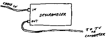
The unit is complete and ready to tune. Hook the unit up to the cable
system as shown below. Be sure to got the cable companies permission before
proceeding with this step. Note: the unit precedes the converter or TV
set. You will need a jumper cable with F59 connectors on each end. Be sure
the input and output is correct.
TUNE UP PROCEDURE
Before tuning you may wish to check your power supply voltage between C24
(+) and the cabinet. This voltage should be a little less than the voltage
across the capacitor itself. With the descrambler hooked up and the power
supply on and the switch in the on position. you can begin tuning. Any
splitters or FM traps on the line should be removed as they attenuate the
signal somewhat and make tuning difficult.
CRUDE TUNING METHOD
This tuning method requires no equipment but the resultant picture quality
is still good. If the unit is moved to a new location retuning may be required.
Tuning consists of simply expanding and contracting the coils of L8, L7,
L1 and L3. Use a non magnetic adjusting tool such as a tooth pick or plastic
tuning tool. First turn the TV to a channel other than the premium channel.
Expand L8, L7 and L1, in that order, while watching the picture.
When horizontal bars begin to move across the screen, then you may have
locked onto the pilot signal pulses. Turn to the premium channel and see
if it locks. If it does, continue tuning until you get a nice clean picture.
If it doesnít lock, then you have tuned to a TV channel and the coils will
probably have to be compressed. Not all the coils will need as much expanding
and It may take several tries to find the pilot. L3 is not tuned with this
method as it is too insensitive.
ADVANCED TUNING METHOD
The difference between the advanced and the crude method is one additional
piece of equipment, a variable attenuator. The one by Winegard, model VA-87,
has been used successfully. It can be purchased from most shops that sell
TV antennas. The attenuator is connected in the line ahead of the descrambler
and initially tuned to the minimum attenuation position. The descrambler
is tuned the same method as described above. The attenuator is then turned
to higher attenuation levels until the premium picture stops locking. The
descrambler is again retuned to lock the picture. This time L3 may have
to be tuned. After a clean picture has again been restored, the attenuator
is again turned up and the descrambler tuned again. Continue this process
until the descrambler can no longer be tuned any better. With this method,
attenuation levels as high as 16 dB can be achieved.
EXPERT TUNING METHOD
The expert method uses both an attenuator and an oscilloscope. The method
is the same as the advanced method except instead of watching the picture
on the TV set, you watch the actual pulse train on the scope. Connect the
scope to the anode of CR2. Tune the descrambler coils until you achieve
nice straight clean pulses increasing the attenuation as needed. Attenuation
levels as high as 24 dB can be achieved with this method.
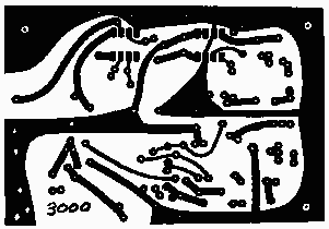
POK 3000 PCB LAYOUT
 [ Back to Plans List ]


